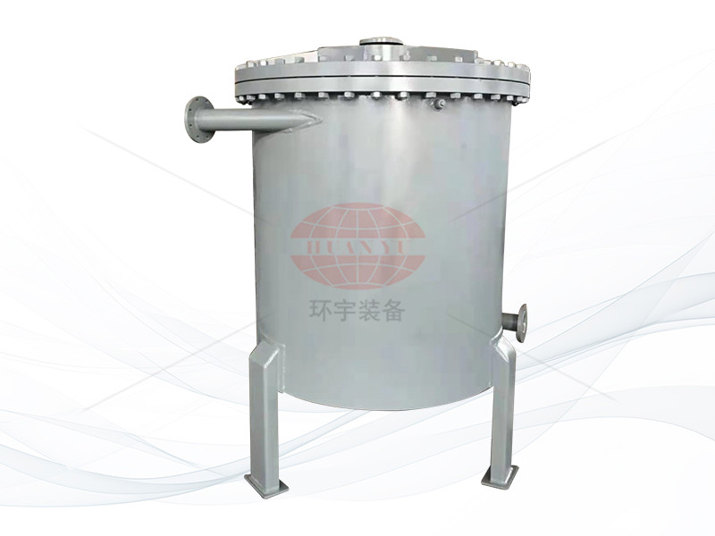
Product overview
Spiral plate heat exchanger is a type of heat exchange equipment suitable for gas gas, gas-liquid, liquid-liquid, as well as for condensation and liquid evaporation heat transfer. This product has the advantages of high heat transfer efficiency, strong self-cleaning ability for dirt, good energy-saving effect, small size, low price, and reliable use.
The product is suitable for industries such as chemistry, petroleum, solvents, pharmaceuticals, food, light industry, textiles, metallurgy, steel rolling, coking, etc. According to the structural form, it can be divided into non detachable (Type I) spiral plate heat exchangers and detachable (Type II, Type III) spiral plate heat exchangers.
Structural performance
1. The equipment is suitable for: gas gas, liquid liquid, gas-liquid convective heat transfer, and can be used for steam condensation and liquid evaporation heat transfer. It can be selected for industrial sectors such as chemical, petroleum, pharmaceutical, machinery, power, light industry, and textile.
2. The equipment is made of two rolled steel plates, forming two uniform spiral channels. The two heat transfer media can flow in full reverse flow, suitable for small temperature difference heat transfer, easy to recover low-temperature heat sources, and can accurately control the outlet temperature.
3. The connecting pipe on the shell is a tangential structure with low local resistance. The curvature of the spiral channel is uniform, and there is no significant reversal of fluid flow inside the equipment, resulting in low overall resistance. Therefore, the design flow rate can be increased to have higher heat transfer capacity.
4. The end face of the spiral channel is welded and sealed, with good sealing performance and reliable structure.
5. It is not easy to maintain, especially when there are problems with the internal panels. Some factories remove all the welds on both ends of the equipment, flatten and weld the panels again, and then roll them up. This consumes too much time, so it is very important to use spiral plate heat exchangers for corrosion prevention.
6. Mechanical cleaning cannot be carried out. Production practice has proven that spiral plate heat exchangers are less prone to clogging compared to general tube heat exchangers, especially suspended particles such as sediment and small shells that are less likely to deposit in the spiral channel. Analyze the reasons for this; One reason is that it is a single channel impurity, and once the deposition in the channel forms a circulating flow, it will increase to the point where it will be washed away. The other reason is that there are no blind spots in the spiral channel, and impurities are easily washed out.
7. Because there are fixed distance columns supporting the spacing between channels in the spiral channel, it is possible to prevent fibrous impurities (such as cotton yarn, grass sticks, leaves, etc.) from entering the interior of the heat exchanger.
8. Strictly control the outlet temperature of the cooling water below the scaling temperature.
9. The commonly used cleaning methods are steam blowing or alkali washing. Steam blowing should be directed towards the connecting pipe to blow out impurities from the equipment.
Basic parameters
The nominal pressure PN of the spiral plate heat exchanger is specified as 0.6, 1, 1.6, and 2.5 Mpa (i.e. the original 6, 10, 16, and 25 kg/cm²) (referring to the maximum working pressure that a single channel can withstand). The test pressure is 1.25 times the working pressure.
The material of the contact part between the spiral plate heat exchanger and the medium is Q235A and Q235AF carbon steel, and SUS321 and SUS304 stainless steel acid steel. Other materials can be selected according to user requirements. Allowable working temperature: t=0~+350 ℃ for carbon steel, t=-40~500 ℃ for stainless steel acid steel, and the temperature and pressure range shall be in accordance with the relevant regulations for pressure vessels. When selecting equipment, appropriate process calculations should be carried out to ensure that the fluid in the equipment channel reaches a turbulent state. (Generally, the liquid flow rate is 1m/Sec and the gas flow rate is 10m/Sec).
A single device cannot meet the usage requirements, and multiple devices can be combined for use, but the combination must comply with the following regulations:
Parallel combination, series combination: equipment and channel spacing are the same.
Mixed combination: one channel in parallel and one channel in series.
Technical parameter
|
Nominal heat exchange area |
Channel Spacing |
Carbon steel |
Stainless steel |
|
Plate thickness |
|
5m² |
6—10 |
4mm |
2~3mm |
|
10m² |
6—10 |
4mm |
2~3mm |
|
20m² |
6—14 |
4mm |
2~3mm |
|
30m² |
10—14 |
4mm |
2~3mm |
|
40m² |
10—14 |
4mm |
2~3mm |
|
50m² |
10—14 |
4mm |
2~3mm |
|
60m² |
14—18 |
4mm |
2~3mm |
|
70m² |
14—18 |
4mm |
2~3mm |
|
80m² |
14—18 |
4mm |
2~3mm |
|
100m² |
14—18 |
4mm |
2~3mm |
|
120m² |
14—20 |
4~5mm |
2~4mm |
|
130m² |
14—20 |
4~5mm |
2~4mm |
|
150m² |
14—20 |
4~5mm |
2~4mm |
|
300m² |
14—20 |
4~5mm |
2~4mm |

